Pilo: Raspberry Pi-Powered Lights-Out Remote Server Management for $60 or less
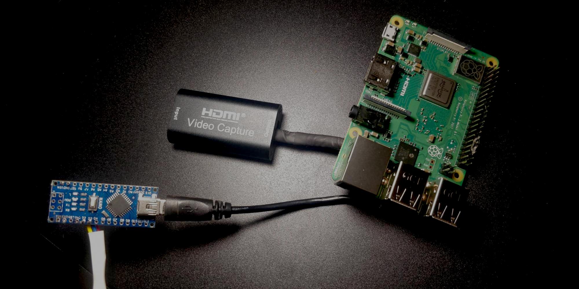 The completed Pilo controller, before final installation. The USB capture card and Arduino Nano USB serial are soldered to the underside of the 3B+.
Like many geeks, I have a “home server” made from off-the-shelf, consumer-grade PC parts, from which I run my weekend programming projects, game servers for friends, this website, and so on. Recently, I had a power event at the house that caused the server to reboot. When the power came back on, the server booted, but it was stuck at the boot screen waiting for me to enter the disk decryption passphrase!
Luckily, I was at home and asleep at the time. Once I woke up and realized something was amiss, I was able to plug in a keyboard and enter the passphrase. But this event got me thinking - what if I wasn’t home at the time? What if I was in another country? What if someday, I move this server outside of my house and need to regularly access the physical screen and keyboard?
In the “real server” world, the solution to this is known as “lights-out management” (LOM). Every major server manufacturer has their own flavor of this, such as HP’s iLO (Integrated Lights-Out). There are even industry standards like IPMI that define common interfaces for LOM implementations. Commonly supported functions for LOM systems include:
- Controlling keyboard and mouse input
- Controlling power button status (so you can restart, shutdown, force off…)
- Seeing the raw video output from the motherboard (even pre-boot - even for BIOS)
- Mounting ISOs as disks
I decided to make my own Raspberry Pi-based LOM that can do some of these things, to help decrease my stress next time I leave my house for an extended period of time. I’d like to introduce Pilo - “Pi Lights-Out”.
Note: This post describes how I arrived at the final design of this system. If you just want the instructions for setting this up on your own, start reading at “Tutorial”.
Building the Keyboard Controller
When I started looking for ways to use my Pi to send keyboard commands to a computer, the problem I discovered was that all of the existing methods rely on using the Raspberry Pi Zero as a USB host, which disables using the onboard USB port for other purposes. Additionally, this method does not work on other boards, like the Raspberry Pi 3B+. This was problematic, because I wanted to use the 3B+ due to the on-board Ethernet - that, and the fact that I had one kicking around from a previous Pi-hole deployment.
A more suitable solution would be to emulate a keyboard via the GPIO pins of the Pi. This would theoretically not affect existing USB devices, and could be used on any model of Pi, not just the Pi Zero. So I started looked into trying to “bit-bang” the USB Human Interface Device protocol via the Pi’s GPIO pins.
I pretty quickly hit a dead end with that. There are many, many existing discussions on the web about bit-banging the USB protocol on the Pi. The consensus seems to be that the Raspberry Pi’s GPIO is too slow to emulate USB, and even if it could output bits fast enough to act as a USB device, the implementation would be extremely buggy because of the non-real-time nature of the Linux OS (read more).
But USB isn’t the only way to send keypresses to a computer - almost a decade before the USB standard was a twinkle in Compaq’s eye, IBM was using the PS/2 standard (not to be confused with the PS2) to connect mice and keyboards to PCs. It’s still not feasible to use the Pi to bit-bang the PS/2 protocol, but we can use an Arduino as a daughterboard, and the ps2dev library can handle the nitty-gritty of the serial protocol for PS/2.
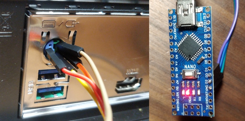
So that’s what I did. The Arduino Nano pictured on the left is plugged directly into the PS/2 combo port on the back of the motherboard (ignore the unused 5V wire, red). Originally, I planned on cutting the end off of a PS/2 cable and making it all nice, but the Goodwill near me didn’t have any PS/2 junk and it turns out that breadboard wires just fit oh-so-snugly into the DIN holes. So this is how it’s gonna be.
The Arduino Nano is flashed with a short program that makes it act as a dumb pipe which blindly shuttles bytes from the Arduino’s USB serial port to the PS/2 connection on the motherboard. This means that all of the logic for which keyboard commands should be sent has to be written on the Pi-side, which is nice, because it means that we should never have to re-flash the Arduino to update some keyboard logic.
Note that currently, Pilo is only built to control keyboard input, since it is oriented towards server use. It would be possible to add PS/2 mouse output with no additional hardware, just 2 or 3 wires for PS/2 mouse CLK, DATA, and GND (unless using combo port). The ps2dev library contains functions for mouse control as well.
Power Control via PS/2
Originally, I thought I was going to have to wire a relay to the motherboard’s RESET pin to allow Pilo to control the computer’s power. This is the approach that diy-ipmi, another similar project, uses. However, while researching the keyboard controller, I rediscovered a long-lost secret of the PS/2 standard: the “ACPI keys”. ACPI, or the Advanced Configuration and Power Interface, is a set of power management standards for PCs. The PS/2 standards define Power, WakeUp, and Sleep key scancodes that can be used to control the power status of the PC - just like the power button on the front of the box, a short-press of the Power key requests the OS to shutdown. However, on my motherboard, a long-press of Power does NOT seem to force the power off.
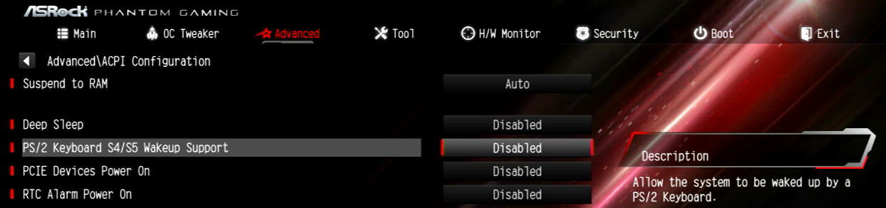
Almost all BIOS support using the ACPI keys to power the system on from a powered down state. Above is what the option looks like in my BIOS (in ACPI, the powered-off state is known as “S5”). With this option enabled, sending the Power scancode will boot the computer up from an off state.
So, now the Arduino has two responsibilities in Pilo: to send regular keypresses to the computer, and to send power commands to the computer. This saves us from having to install a relay for the motherboard’s RESET pin.
Capturing Video Output
My server has a GPU with HDMI output, so I decided to use a USB HDMI capture card to get the video feed for Pilo. I found one on Amazon for about $15. When connected to the Pi, it acts as a regular USB webcam, available under /dev/videoX.
Before this project, I had no experience with streaming video over the web. I decided to use uv4l (“Userspace Video4Linux”)’s uv4l-server component to set up an HTTP video server. uv4l makes it easy to set up a simple MJPEG stream, which is the goofiest possible video stream - each frame of the stream is a full JPEG image, sent to you in real time. As you can imagine, it’s not the lightest on bandwidth, but it is easy to embed - all web browsers support embedding it in an <img> tag: <img src="/stream.mjpeg"/>
I configured the uv4l-server to only listen on localhost, with the idea that I could reverse-proxy connections to the video stream to provide security.
Creating the application
For the Pilo interface, I decided to go with a web app, instead of something like VNC, or the actual IPMI protocol. This was mostly due to my background in web development, and the fact that the app can be accessed with a web browser, something every computer has installed. Here is a short video showing the completed Pilo app in action:
You can find the GitHub repo for Pilo here. It consists of two major components:
frontend- uses vanilla HTML/CSS/JS to display the interface, translate keypresses, and communicate with the server via websocketsserver- the HTTP server, written in Node.js. Authenticates requests using HTTP basic auth, communicates with the keyboard controller via theserialportlibrary, and manages reverse-proxying of theuv4l-servervideo stream
There are also end-to-end tests in the e2e folder which use Cypress to test the application in real web browsers. This runs against Firefox and Chrome on every commit to CI via a GitHub Actions workflow.
The README contains information on building and testing the project if you are interested in contributing. Built packages are also published to npm for production use.
Packaging the Pilo
One of my goals when building Pilo was to make it small enough to fit inside of my server case. Check out these photos to see how it fit in:
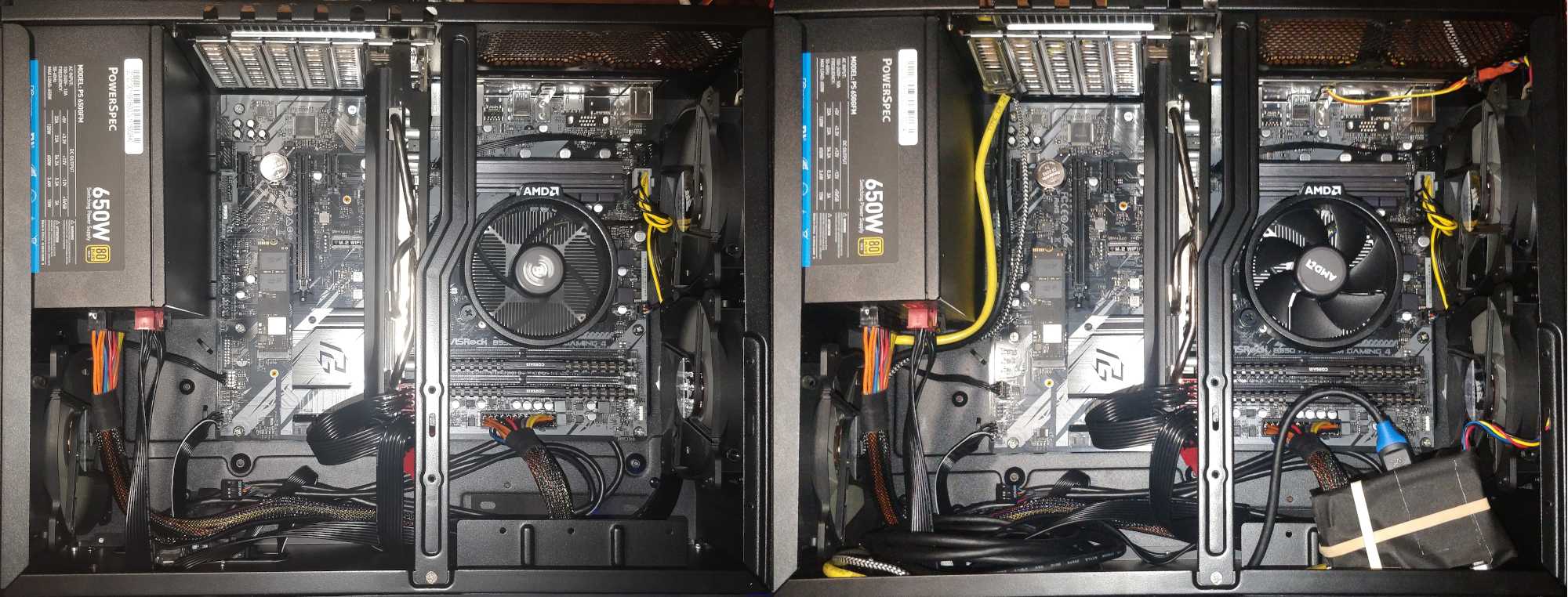 Left: Server case before embedding the Pilo. Right: Server case after embedding the Pilo. HDMI, Ethernet, and micro-USB power are routed through the left-most PCI-E slot, while PS/2 is routed through the I/O shield in the top-right. The Pilo itself sits atop a ledge in the bottom-right of the image.
Here are some pictures of how the final assembly was made:
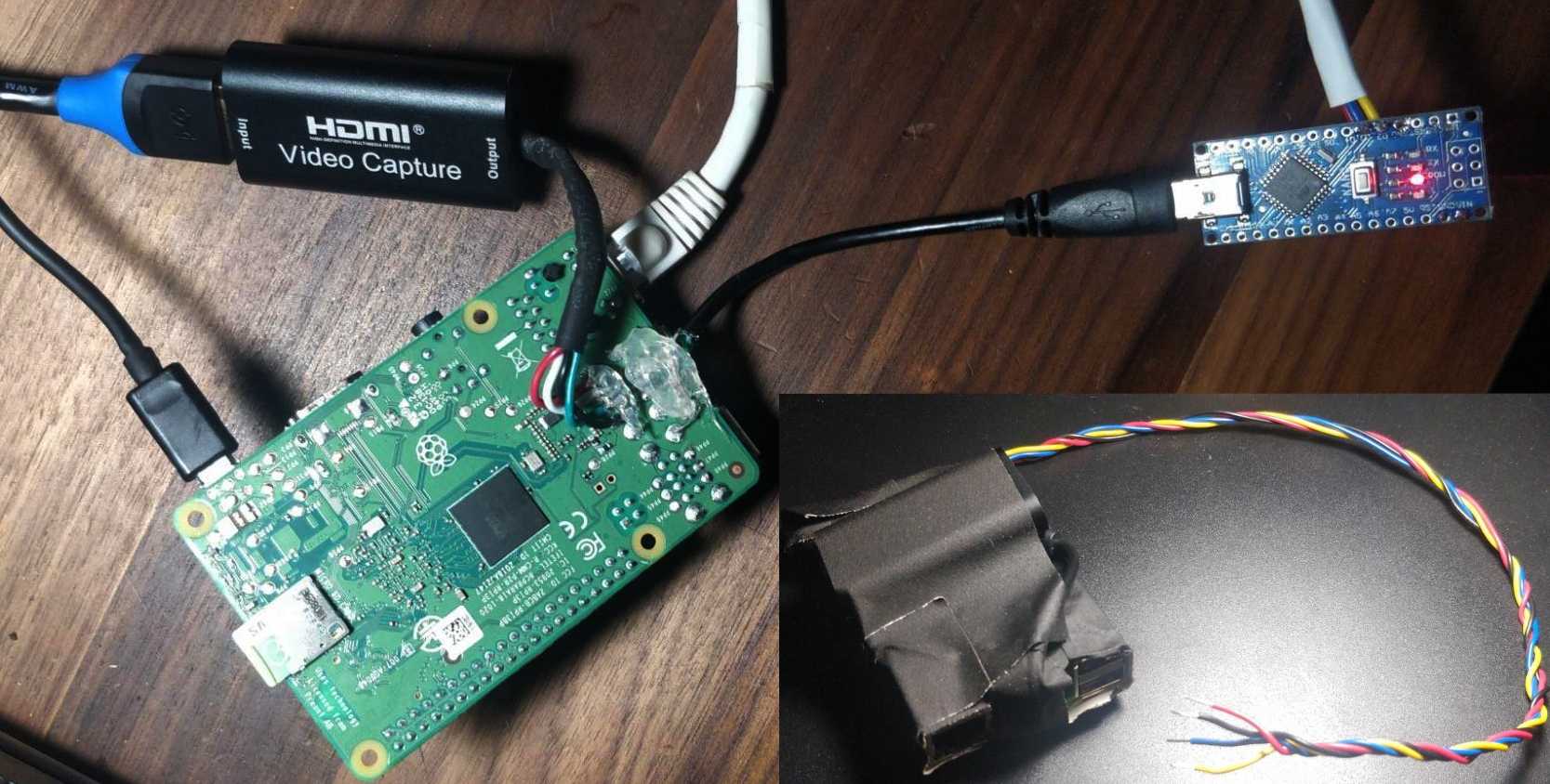 Outer photo: Pi with the USB devices soldered on to the underside to save space. Inset photo: Final package taped up and ready for install, with PS/2 cable coming out. Hot glue and tape make me the solderer I ain’t.
The completed package fits within a bounding box only slightly larger than the Pi itself, about 88mm x 60mm x 20mm, which means the Pilo can fit conveniently into a standard 3.5” hard drive bay.
Tutorial
Parts List
- Raspberry Pi 3B+ ($25 at MicroCenter, $35 everywhere else)
- Or other micro linux computer - even a Pi Zero could work, but you’d be using WiFi, and you’d need a USB hub for the Arduino serial, or set up the Arduino serial via GPIO
- Arduino Nano (Amazon has them at $16.99 for 5 - $3.40 each)
- Any other 5V-logic-level Arduino would work as well. Needs to be 5V or have the CLK + DATA outputs converted from 3V3 to 5V, since the PS/2 serial connection expects 5V.
- USB HDMI Capture Card (
video4linuxcompatible - most cards are) (Amazon, $13.99) - (optional) PS/2 plug, to make a tidy connection
- Supplies: Wires, soldering iron if you need to solder, microSD card and micro-USB power supply for the Pi…
Comes out to roughly $60 if you buy everything at it’s cheapest, $50 if you’re lucky enough to live near a MicroCenter.
Setup
- Before getting started, make sure you have your devices ready:
- Have a Debian-based OS like Raspbian or DietPi installed on the Pi’s microSD card.
- Flash the
serial_to_ps2program to your Arduino Nano.
- Connect everything according to this beautiful wiring diagram:
┌───────────────────────────┐ │ Ethernet├───────────────────────────┤Ext. Ethernet │ RasPi 3B+ USB Power In├───────────────────────────┤Ext. 5V Power │ (or other) USB Port├───────────┐ │ USB Port├──────┐ │ └───────────────────────────┘ │ │ │ │ ┌────────────────────────────┐ ┌───────────────────────────┐ │ └─┤USB Plug HDMI Capture Card │ │ Server HDMI Out├──────┼──────┤HDMI In │ │ PS/2 Keyboard Port├───┐ │ └────────────────────────────┘ └───────────────────────────┘ │ │ │ │ │ │ ┌────────────────────────────┐ │ └──────┤USB Port │ │ ┌──┤D2 (DATA) Arduino Nano │ └──────┤──┤D3 (CLK) (or other) │ └──┤GND (GND) │ └────────────────────────────┘- Connect D2 (DATA), D3 (CLK), and GND from the Arduino Nano directly to the respective pins of the PS/2 keyboard port on the motherboard. Consult the Internet for a reference pinout.
- You can dress this up by scavenging a spare PS/2 pigtail and stripping the end, but breadboard wires also fit snugly into the DIN port.
- Turn off your server before connecting or disconnecting anything to/from the PS/2 port. The PS/2 port was not designed with hotplugging in mind. You risk damaging your components and your OS most likely won’t detect a hot-plugged PS/2 device, so don’t bother.
- Do not connect the +5V pin from the PS/2 port to VIN on the Arduino - this is a bad idea for a myriad of reasons.
- Connect D2 (DATA), D3 (CLK), and GND from the Arduino Nano directly to the respective pins of the PS/2 keyboard port on the motherboard. Consult the Internet for a reference pinout.
- Set up the MJPEG streaming server for the USB HDMI capture card.
- Follow the instructions on the
uv4lwebsite to install theaptsources foruv4l. Note for Debian Buster users: There is not auv4laptrepo for Buster yet, but the Stretch repo seem to work fine on Buster. - Update the
aptindex, and install the required packages:apt update apt install uv4l uv4l-server uv4l-uvc uv4l-mjpegstream - Retrieve your USB HDMI capture card’s ID by running
lsusb. It should be a hexadecimal string like1a2b:3c4d. - Start the
uv4lserver listening on127.0.0.1:9000, substituting your device ID for1a2b:3c4dbelow:uv4l --driver uvc --device-id '1a2b:3c4d' --auto-video_nr --server-option '--port=9000' --server-option '--bind-host-address=127.0.0.1'You should be able to access a MJPEG stream of the USB HDMI capture card locally on the Pi at
http://127.0.0.1:9000/stream/video.mjpeg. You will not be able to access this over the network, since it is bound to localhost by the--bind-host-address. - Set the command from (4) to run on every boot, for example, by adding it to
/etc/rc.local.
- Follow the instructions on the
- Now, it is time to generate your auth credentials. Follow this algorithm:
- Think of a secure username and a password. For example:
foo,bar - Join them with a colon. For example:
foo:bar - SHA256 the result. For example:
a765a8beaa9d561d4c5cbed29d8f4e30870297fdfa9cb7d6e9848a95fec9f937 - This is your
AUTH_SHA.
- Think of a secure username and a password. For example:
- Install Node.js and npm:
apt install nodejs npm - Install the latest distribution of
pilofromnpm:npm install --global piloYou may need to pass
--unsafe-permsif installing asroot. - You can now start
piloon port 3000 by running the command withAUTH_SHAset in an environment variable:AUTH_SHA=a765a8beaa9d561d4c5cbed29d8f4e30870297fdfa9cb7d6e9848a95fec9f937 pilo &You should now be able to access Pilo at
http://<your-pi-IP>:3000/, using the username and password you created earlier. - Add the above command to
/etc/rc.localto run it on boot.
Comments on "Pilo: Raspberry Pi-Powered Lights-Out Remote Server Management for $60 or less"